







CUSTOMER SERVICE
www.sensors.vn
Admin@sensors.vn
www.cambien.com.vn
MOTOR VIBRATION SENSOR
Date 19/Oct/2026 at 10:51 AM - View: 26
WHAT PROBLEMS CAN MOTOR VIBRATION CAUSE?
Vibration can indicate that mechanical components are experiencing problems, such as imbalance, shaft misalignment, loose connections, or bearing damage. Specifically:
Bearing and mechanical component damage
Prolonged vibration can increase dynamic loads on bearings, shafts, and rotating components. If the vibration is caused by worn or damaged bearings, it may continue to increase and accelerate equipment deterioration.
Shaft misalignment and imbalance
A misaligned rotating shaft or an unbalanced rotor can generate continuous vibration while the motor is operating. This condition increases loads on bearings, couplings, and drive components, causing accelerated wear.
Loose connections and structural damage
Excessive vibration can loosen bolts, mounting bases, and mechanical connections. Conversely, loose connections can also increase vibration, creating a cycle that progressively worsens equipment condition.
Abnormal motor vibration can be an early warning sign of mechanical faults, increasing the risk of wear, equipment failure, and unexpected shutdowns. Installing a motor vibration sensor helps businesses detect these changes early, inspect equipment proactively, and reduce the risk of serious failures.
→ See also: Vibration sensors and four common types
KEY FEATURES OF MOTOR VIBRATION SENSORS
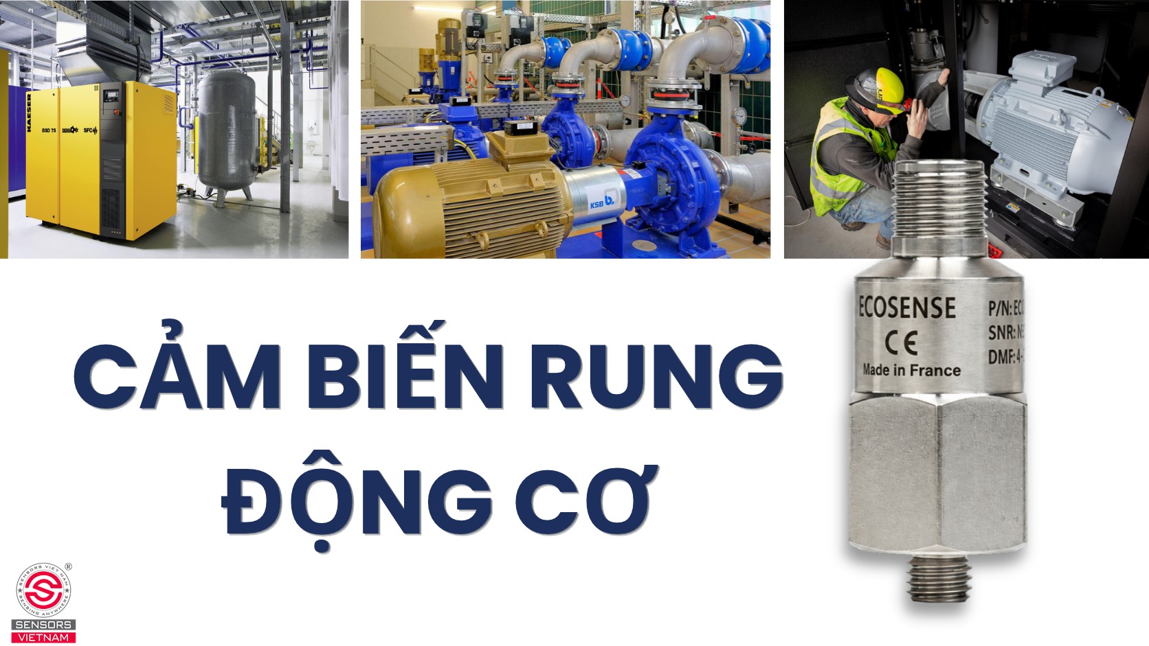
A motor vibration sensor is a device used to detect and measure vibration generated during electric motor operation. It is typically installed on the motor housing, near the bearings, or at other locations where significant vibration may occur.
When a motor operates, its internal components may generate vibration due to rotational movement, imbalance, shaft misalignment, loose mechanical connections, or bearing damage. The sensor detects this vibration and converts it into an electrical signal for analysis by a controller, PLC, or monitoring system.
Depending on the sensor type, the device can measure vibration acceleration, expressed in m/s² or g, vibration velocity, expressed in mm/s, or vibration displacement, expressed in µm or mm. Its primary purpose is to monitor motor operating conditions, detect abnormal signs, and support predictive maintenance before serious equipment failures occur.
HOW DOES A MOTOR VIBRATION SENSOR WORK?
The basic operating principle of a motor vibration sensor involves the following four steps:
Step 1: Detecting vibration from the motor
The sensor is mounted on the motor housing or at a suitable measurement point to detect vibratory motion generated while the motor is operating.
Step 2: Converting vibration into an electrical signal
The sensing element detects mechanical movement and generates a corresponding electrical signal. The conversion method depends on the sensor technology:
- A piezoelectric accelerometer contains a piezoelectric element and a seismic mass. When the motor vibrates, the force acting on the piezoelectric element generates an electrical charge, producing a signal related to vibration acceleration.
- A MEMS accelerometer detects the movement of a microscopic mechanical mass, which changes an electrical parameter and allows acceleration to be determined.
- An electrodynamic vibration velocity sensor generates an induced voltage through the relative movement between a magnet and a coil. The resulting signal corresponds to vibration velocity.
Step 3: Processing and transmitting the signal
The electronic circuitry processes the signal and, depending on the device, converts it into a 4 to 20 mA signal, a 0 to 10 V signal, or a digital output.
Step 4: Monitoring and generating alarms
A PLC, monitoring device, or BMS receives the data and compares it with configured thresholds to generate alarms or initiate control actions if the system has been configured to do so.
APPLICATIONS OF MOTOR VIBRATION SENSORS
Motor vibration sensors are widely used in the following practical applications:
Vibration sensors for fan motors in HVAC systems
In HVAC systems, vibration sensors are typically installed on the motor housing, near the bearings, or at suitable measurement points on the fan assembly to monitor operating conditions. Installing a vibration sensor helps detect early signs of fan problems, such as fan blade imbalance, bearing deterioration, shaft misalignment, or drive belt issues.
This application is particularly useful for supply air fans, return air fans, and ventilation fans that operate continuously in commercial buildings, hospitals, and industrial facilities.
Vibration sensors for water pump motors
These sensors monitor vibration associated with bearing condition, imbalance, coupling misalignment, and other mechanical problems. Vibration monitoring is used in cooling water pumps, HVAC circulation pumps, water supply pumps, and wastewater treatment pumps to help detect abnormal conditions early, reduce the risk of equipment damage, and prevent operational disruptions.
Vibration sensors for air compressor and chiller motors
In compressed air systems and industrial refrigeration systems, vibration sensors are used to monitor motors and rotating components in compressors. For chillers, the monitoring approach should be selected according to the specific compressor design and system requirements. This application helps maintenance teams monitor equipment condition, plan inspections, and reduce the risk of unexpected downtime.
Vibration sensors for conveyor motors and gearboxes
In production lines, vibration sensors can be installed on motor bearing housings, shaft support bearings, or gearbox housings to monitor the condition of drive assemblies. Abnormal vibration may result from rotor imbalance, bearing deterioration, damaged gears, or loose mechanical connections.
This application is suitable for conveyor systems in manufacturing plants, cement plants, mining facilities, and material handling systems, where motor failure can disrupt the entire production line.
HOW TO INSTALL A MOTOR VIBRATION SENSOR
When installing a motor vibration sensor, the most important considerations are selecting the correct measurement location, securing the sensor firmly, and connecting the signal correctly to the monitoring system.
Determine the sensor installation location
The sensor is commonly installed on the motor bearing housing because this location provides a relatively clear transmission path for vibration from the shaft and bearings to the machine structure. The following locations should be considered:
- Drive end: Near the shaft end connected to the coupling or driven equipment.
- Non drive end: At the opposite end of the motor, which is generally suitable for monitoring vibration at that bearing location.
- Driven equipment assembly: For fans, pumps, or gearboxes, an additional sensor may be required at the corresponding bearing support to distinguish motor vibration from vibration generated by the driven equipment.
Prepare the mounting surface
After selecting the installation location, inspect the contact surface between the sensor and the motor.
- Select a solid, relatively flat metal surface near the bearing.
- Remove dirt, oil, grease, and coatings that may interfere with mechanical contact.
- Avoid installing the sensor on thin covers, flexible metal panels, or components that do not adequately represent the vibration being measured.
- Do not place an elastic pad between the sensor and the mounting surface.
Secure the sensor to the motor
Three common installation methods are direct stud mounting, magnetic mounting, and the use of specialized adhesive or mounting adapters. When tightening the sensor, follow the torque specifications provided in the documentation for the specific model. Do not apply a single torque value to all sensor types.
Connect the signal cable and power supply
After securing the sensor, connect it to the controller or monitoring system. It is recommended to use shielded cables, ground the cable shield at one end, and route the sensor cable separately from power cables connected to variable frequency drives.
→ See also: ECO-VS vibration sensor series
Hot news





SENSORS VIETNAM CO., LTD
VAT CODE: 0313 355 473
Head Office: 03rd Floor, Indochina Tower, 04 Nguyen Dinh Chieu, Tan Dinh Ward, Ho Chi Minh City, Vietnam.
HCM Branch: 92/14/9A Vuon Lai Str., An Phu Dong Ward, Ho Chi Minh City, Vietnam.
Hanoi Branch: S106 Tower, Vinhomes Smart City, Tay Mo Ward, Hanoi City, Vietnam.

® Registered trademark – National Office of Intellectual Property Vietnam
OUR SERVICES
Specializing in the import and distribution of industrial sensors.
Sensors for HVAC/R systems and building automation applications.
Supplying gauges, transmitters, switches, controllers, PLCs, HMIs, and gas detectors.
Providing integrated consulting services for sensor and controller systems.


CONTACT US
Email: sales(at)sensors.vn
Hotline: +84 0911 660 660
Asia Commercial Bank Account (ACB):
VND: 357 246 888 | USD: 1357 246 888
Support Online ZALO Official Account
(From 8:00 am to 5:00 pm)





SENSORS VIETNAM CO., LTD
- Specialized in the import and distribution of sensors and controllers.
- Integrated data acquisition systems and industrial communication solutions.
- Design and installation of smart home systems and industrial equipment.
- Stack lights, signal beacons, LED warning horns, and RGB warning lights.