





CUSTOMER SERVICE
www.sensors.vn
Admin@sensors.vn
www.cambien.com.vn
WHAT IS 0-10V SIGNAL?
Date 01/Oct/2026 at 04:15 PM - View: 8
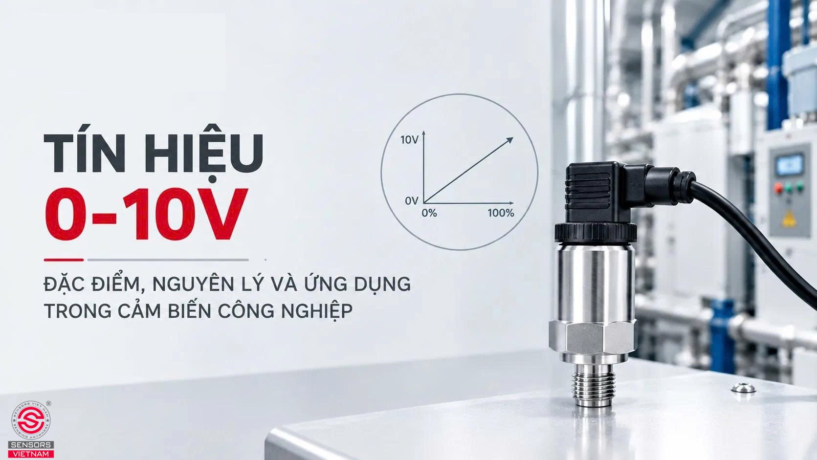
From 0 to 10V sensors used to measure air duct pressure to 0 to 10V controllers sending commands to AHU fan variable frequency drives, this voltage signal standard is widely used in modern HVAC systems. This article summarizes its key characteristics, operating principle, comparison with 4 to 20mA signals, noise protection and voltage drop considerations, as well as practical wiring and testing methods.
OVERVIEW OF THE 0 TO 10V SIGNAL
A 0 to 10V signal is a type of analog signal in which the value being transmitted is represented by a DC voltage level ranging from 0 to 10 volts. The higher the voltage, the greater the represented value. A pressure sensor may output 0V when the pressure is at the lower end of its measurement range and 10V when the pressure reaches the upper end of the range. Conversely, a 0 to 10V controller can send 5V to a variable frequency drive to command a fan to operate at approximately half speed.
In HVAC applications, this standard is widely used because of its simple structure, ease of testing with a multimeter, and compatibility with many building devices, including temperature sensors, humidity sensors, CO2 sensors, damper actuators, water valves, fan variable frequency drives, pumps, and dimmable lighting systems.
CHARACTERISTICS OF THE 0 TO 10V SIGNAL
The 0 to 10V signal varies continuously
Unlike a digital signal, which has only two states, ON or OFF, a 0 to 10V signal can take any value between the two ends of the signal range. Voltages such as 3.7V, 6.25V, or 8.9V are all valid values, with each value corresponding to a specific state of the measured or controlled variable.
This continuous characteristic allows the system to provide smooth control. For example, with a fresh air damper, using only two positions, fully closed and fully open, can cause airflow to change abruptly and result in room temperature fluctuations. With a 0 to 10V signal, the controller can position the damper at exactly 35 percent when required and gradually increase the opening as the load changes. This helps maintain more stable temperatures, reduces frequent equipment cycling, decreases mechanical wear, and saves energy.
0 to 10V voltage range
The values 0 and 10 represent the two boundaries of the signal range. A voltage of 0V generally corresponds to the minimum value, while 10V corresponds to the maximum value of the represented variable. The conversion between voltage and the physical variable is linear, meaning that the two values are directly proportional.
For example, consider a 0 to 10V temperature sensor with a measurement range from 0 to 50°C. Each volt then represents 5°C. A reading of 4V means a temperature of 20°C, while 7.5V corresponds to 37.5°C. The general formula is simple:
Measured value = voltage / 10 × measurement span + lower range value
One important point is that many devices allow the operating range to be adjusted. Although both devices use the 0 to 10V standard, one device may operate only from 2V to 10V for control, while a voltage below 2V may be interpreted as an OFF state or a safe position.
 OPERATING PRINCIPLE OF THE 0 TO 10V SIGNAL
In principle, this is information transmission using voltage. The transmitting device generates a voltage level proportional to the value being transmitted. The receiving device has a very high input impedance, typically several tens of kilohms or higher, so it draws very little current. As a result, the current flowing through the circuit is extremely small, and the receiver is primarily concerned with the voltage difference between the signal wire and the common wire.
Two common device types are sources and loads. A source device, such as a 0 to 10V sensor or controller, generates the voltage. A load device, such as a variable frequency drive or actuator, reads that voltage. One output can typically be connected in parallel to multiple inputs, provided that the total load does not exceed the output's current capacity.
Because the signal is transmitted through voltage, it is affected by cable resistance and electromagnetic interference. Long cables can cause a small voltage drop, while noise sources such as high power variable frequency drives can introduce unwanted voltage into the signal line.
APPLICATIONS OF THE 0 TO 10V SIGNAL
The 0 to 10V signal is used on both sides of a control loop: the measurement side, from sensors to controllers, and the control side, from controllers to actuators.
On the sensor side, common devices using 0 to 10V signals include:
- Temperature sensors
- Humidity sensors
- Differential pressure sensors
- Air duct pressure sensors
- CO2 sensors
- Air quality sensors
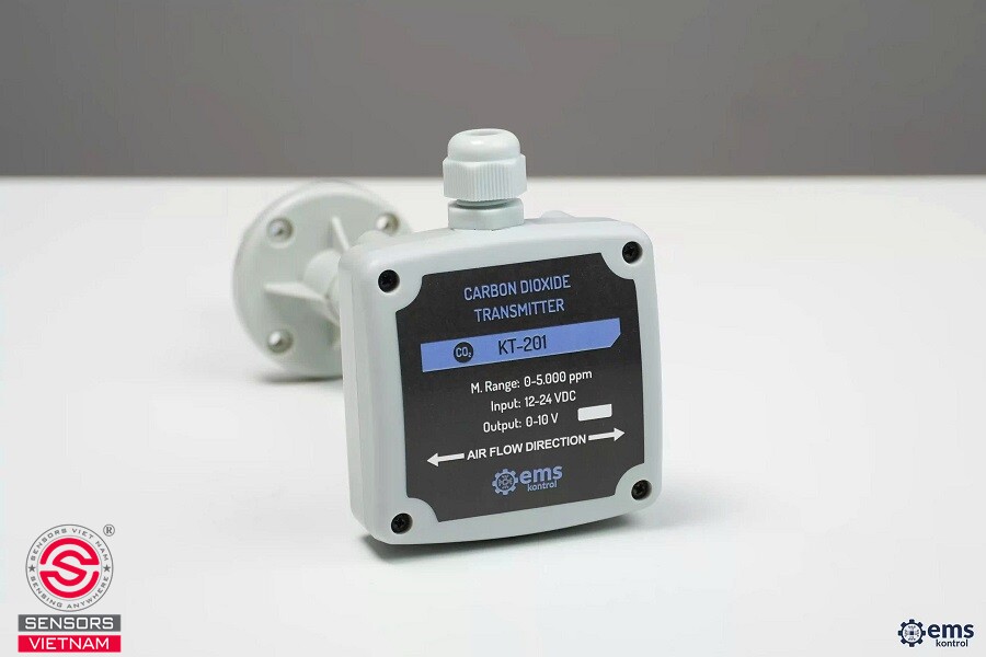
For example, a 0 to 10V CO2 sensor installed in a meeting room can transmit the measured CO2 concentration to the building control system, which can then determine whether additional fresh air is required, enabling demand controlled ventilation based on actual occupancy conditions.
On the control side, a 0 to 10V controller can command a variable frequency drive to adjust the speed of an AHU fan, exhaust fan, or chilled water pump. It can also control damper actuators and two way or three way water valves to regulate the flow of fluid through heat exchange coils. In control panels for EC fans, a 0 to 10V signal is a common method for setting rotational speed without directly modifying the power circuit.
In addition, this standard is widely used in lighting systems, where LED drivers receive a 0 to 10V signal to adjust brightness, and in building automation systems where multiple building services are integrated into a single monitoring platform. Its widespread adoption allows engineers to integrate equipment from different manufacturers without requiring complex communication protocols.
HOW TO WIRE A 0 TO 10V SIGNAL
The basic wiring process consists of three groups of wires: the power supply, if required by the device, the signal wire, and the common wire. Terminology may vary between manufacturers, but common designations include AI or AO for analog input or output, U or Y for the voltage signal, and GND, COM, or M for the common wire.
Case 1: Connecting a 0 to 10V sensor to a controller
Supply power to the sensor according to the voltage specified on the device label. Connect the sensor signal terminal to the analog input of the controller. Connect the sensor GND terminal to the corresponding GND terminal on the controller. Finally, configure the input type as 0 to 10V voltage input and define the measurement conversion range.
Case 2: Connecting a 0 to 10V controller to a variable frequency drive or actuator
Connect the analog output of the controller to the speed or position input of the actuator, together with the common wire. For a variable frequency drive, the analog input is typically located within the control terminal section. The drive parameters must be configured to select the analog signal as the frequency reference source and define the corresponding voltage range. Some variable frequency drives also provide a built in 10V supply terminal, which is convenient when an external potentiometer is used for manual speed adjustment.
Testing after wiring
Use a multimeter to measure the voltage between the signal wire and the common wire. Change the setpoint or stimulate the sensor, then check whether the voltage changes according to the expected relationship. For an actuator, command 0V, 5V, and 10V levels and verify whether the actual position corresponds correctly. This testing step helps identify incorrect wiring, an incorrect signal range, or a missing common wire before the system enters operation.
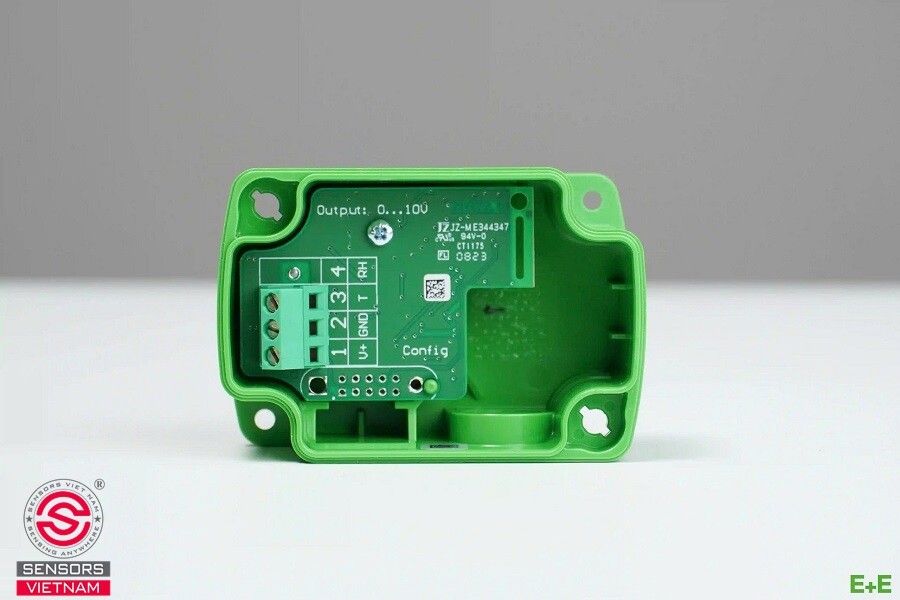 0 TO 10V INDUSTRIAL TRANSMITTER SOLUTIONS FROM SENSORS VIETNAM
Sensors Vietnam provides 0 to 10V industrial transmitter solutions for common measurement requirements including pressure, differential pressure, temperature, humidity, CO2, and flow. Devices are recommended according to specific applications, from chilled water pipe pressure monitoring and cleanroom differential pressure control to air duct temperature measurement and tank level measurement.
Technical specifications of the EE10 M1A3D1 room temperature and humidity sensor
- Model: EE10 M1A3D1
- Function: Temperature and humidity measurement
- Temperature measurement range: 0 to 50°C
- Humidity measurement range: 0 to 100%RH
- Output: 0 to 10V
- Integrated display
- Origin: Austria
- Warranty: 12 months with one to one replacement
- CO and CQ: Fully provided
Technical specifications of the EE431 M3A3L115 0 to 10V water pipe temperature sensor
- Model: EE431 M3A3L115
- Temperature measurement range: 0 to 50°C
- Output: 0 to 10V
- Probe length: 115mm
- Warranty: 24 months official warranty
- Certificates: Full CO and CQ documentation
- Origin: E+E ELEKTRONIK, Czech Republic
For more detailed consultation about 0 to 10V signals or to order sensors with 0 to 10V outputs, please contact Sensors Vietnam directly via hotline 0911 660 660 or visit the websites https://cambien.com.vn/ and https://www.sensors.vn/.
Hot news


SENSORS VIETNAM CO., LTD
VAT CODE: 0313 355 473
Head Office: 03rd Floor, Indochina Tower, 04 Nguyen Dinh Chieu, Tan Dinh Ward, Ho Chi Minh City, Vietnam.
HCM Branch: 92/14/9A Vuon Lai Str., An Phu Dong Ward, Ho Chi Minh City, Vietnam.
Hanoi Branch: S106 Tower, Vinhomes Smart City, Tay Mo Ward, Hanoi City, Vietnam.

® Registered trademark – National Office of Intellectual Property Vietnam
OUR SERVICES
Specializing in the import and distribution of industrial sensors.
Sensors for HVAC/R systems and building automation applications.
Supplying gauges, transmitters, switches, controllers, PLCs, HMIs, and gas detectors.
Providing integrated consulting services for sensor and controller systems.


CONTACT US
Email: sales(at)sensors.vn
Hotline: +84 0911 660 660
Asia Commercial Bank Account (ACB):
VND: 357 246 888 | USD: 1357 246 888
Support Online ZALO Official Account
(From 8:00 am to 5:00 pm)





SENSORS VIETNAM CO., LTD
- Specialized in the import and distribution of sensors and controllers.
- Integrated data acquisition systems and industrial communication solutions.
- Design and installation of smart home systems and industrial equipment.
- Stack lights, signal beacons, LED warning horns, and RGB warning lights.